
Connections and interfaces
A connection relates model features. An interface relates ports. The relationship records the endpoints; positioning two presentations near one another does not create it.
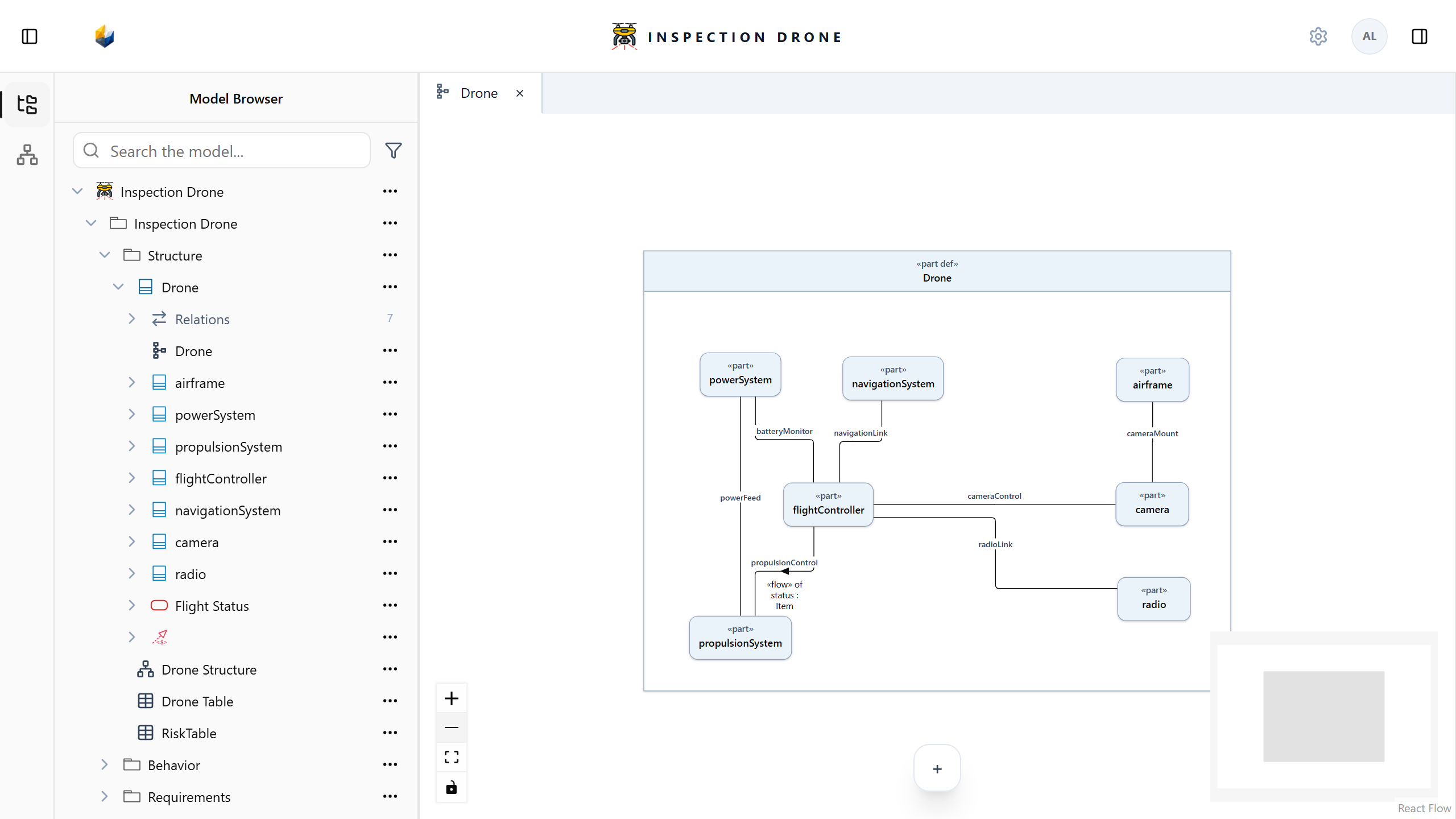
What you need
Use an editable model with two parts presented in a static InterconnectionView. Parts and Diagrams explain how to prepare them.
Create a connection
- Open the interconnection Diagram.
- Select the source part and choose connection in the small toolbar beside it.
- Click the existing target part.
- Select the new line, or find the relationship under its owner’s Relations in the Model Browser.
- Enter a descriptive name in the inspector.
Check: the inspector identifies the intended endpoints. The relationship remains in the model when you select something else.
If connection is missing, check the view kind, selected node, and model editability. Start from a source node and click an existing target; clicking empty space can start creating another element instead.
Relate ports
Prepare the ports and present them on their owning parts.
Select the source port, choose the interface tool, then select the target port. Inspect the resulting relationship to confirm its endpoints.
Check: the relationship connects the intended ports, rather than the containing parts. Use the tool appropriate to those endpoint kinds.
Describe transferred content
A connection identifies its ends. A flow adds transferred content and routes through reachable endpoint features.
Connection names describe modeling intent. Recording these relationships does not calculate electrical or mechanical behavior.

